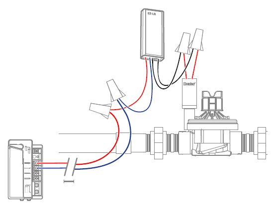
Connect to Controller
- Install decoder in valve box near or together with valve or relay.
- Connect decoder red and blue wires to two-wire path from controller (does not matter which goes where).
- Connect decoder black wires to solenoid or relay (does not matter which goes where).
- Secure all splices with waterproof connectors.
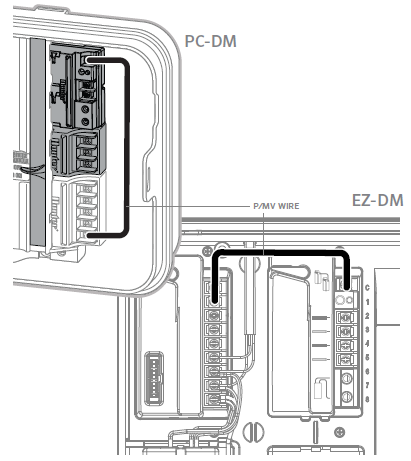
P/MV Connection
- Connect jumper wire from P/MV on controller power module to P/MV terminal on decoder output module.
- Install MV decoder on two-wire path.
Distance to Module (Feet)
| Wiring Table | ||||
|---|---|---|---|---|
| American Wire Gauge | EZ-1 one active solenoid | EZ-1 two active solenoids | EZ-LR one active solenoid | EZ-LR two active solenoids |
| 18 AWG | 947' | 473' | 1,894' | 947' |
| 16 AWG | 1,506' | 753' | 3,012' | 1,505' |
| 14 AWG | 2,395' | 1,197' | 4,790' | 2,394' |
| 12 AWG | 3.808' | 1,903' | 7,616' | 3,807' |
| 10 AWG | 6,053' | 3,025' | 12,107' | 6,051' |
IMPORTANT: Distances in the Wiring Table are calculated based on 60 Hz for American Wire Gauge, and 50 Hz for International, with wire temperature of 122°F (50°C), and a 10% safety factor.
Operating Specifications
- Two wire path input voltage: ~24 VAC, 50/60 Hz
- EZ-LR output voltage: Proprietary high-frequency, low-voltage output for normal AC solenoids.
- A standard voltmeter is not accurate for the EZ-LR output. To verify proper output, the decoder activity light and a known-good solenoid are recommended.
- Enclosure: IP68 (submersible)
Still need help? We're here.
Tell us what you need support with and we'll find the best solution for you.