- Using a hole saw, cut a 3¼" (8.25 cm) diameter hole in the valve box lid.
- Unthread the transmitter retainer nut and feed the transmitter through the hole in the valve box lid so the mushroom cap is exposed.
- Secure the transmitter in place by threading the transmitter retainer nut clockwise until snug against the valve box lid ribs.
- Using the included waterproof connectors, splice the white wire from the transmitter to the white wire from the HC Flow Meter. Then splice the transmitter blue wire to the HC Flow Meter blue wire.
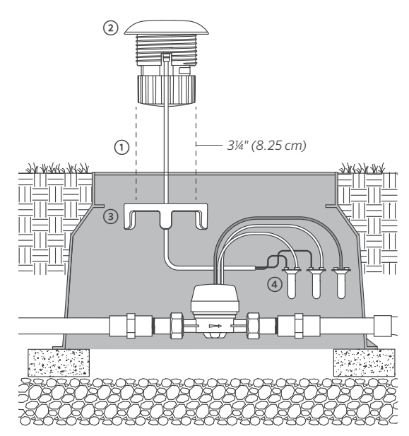
IMPORTANT:Cap the red wires from the flow meter with a waterproof splice. This wire is not used.
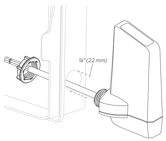
- The Wireless HC Flow Receiver mounts to and is powered by its host controller.
- For best results, mount the receiver through one of the side knockouts on the controller. Use a ⅞" (22 mm) hole saw to remove the knockout. Feed the wires and threaded nipple through the knockout into the controller, and secure in place with the receiver retaining nut.
- Connect the two yellow wires to either 24 VAC
terminals. - Connect the white and blue wires to the sensor
terminals.
The transmitter and receiver are preconfigured for wireless communication right out of the box. After applying power to either the transmitter or receiver, wait a minimum of 10 seconds for the power-up sequence to complete. During this time, there will be one or more green LED blinks before the unit is ready for operation. When flow is occurring, the transmitter will transmit flow sensor data at a maximum rate (depending on flow) of once every 5 seconds. The receiver LED will flash green at the same rate to indicate that flow is occurring.
The receiver LED will flash red twice every 3 seconds to indicate a low or discharged battery. This battery status update will occur only during flow conditions.
When multiple controllers and sensors are within close proximity of one another, users should change the radio channels to prevent cross-talk between the transmitters and receivers. There are eight dip switch positions within both the transmitter and receiver, labeled as 1–8. The factory default setting for both the transmitter and receiver has dip switch position 1 set to ON, and all other dip switches set to OFF.
The 8 dipswitches are used to change the channel within the 900 MHz range used in the WHCFLOW radio. The switch can be at any setting but the receiver and transmitter would need to match (e.g; receiver 2-ON and transmitter 2-ON).
To change the channel, simply change the dip switch positions. Example: Using a flathead screwdriver, flip dip switch position 1 to OFF, and flip switch position 2 to ON (do this for both the transmitter and receiver).
Still need help? We're here.
Tell us what you need support with and we'll find the best solution for you.